Logic Gates
Logic Gates
Logic gates are fundamental building blocks of digital circuits, performing basic logical operations on binary inputs to produce a single output, and include types like AND, OR, NOT, NAND, NOR, XOR, and XNOR.
Logic Gates:
Logic Gates with truth table:

What are Logic Gates?
- Logic gates are electronic circuits that implement Boolean functions, meaning they perform logical operations on binary inputs (0 or 1) to produce a binary output.
- They are the basic building blocks of digital circuits, used to create more complex systems.
- The output of a logic gate depends on the logical relationship between its input(s).
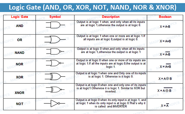
Types of Logic Gates:
- Basic Logic Gates:
- AND Gate: The output is 1 only if all inputs are 1.
- OR Gate: The output is 1 if at least one input is 1.
- NOT Gate: The output is the inverse of the input (0 becomes 1, and 1 becomes 0).
- Derived Logic Gates:
- NAND Gate: The output is the inverse of an AND gate (NOT AND).
- NOR Gate: The output is the inverse of an OR gate (NOT OR).
- XOR Gate (Exclusive OR): The output is 1 if the inputs are different.
- XNOR Gate (Exclusive NOR): The output is 1 if the inputs are the same.
Universal Logic Gates:
NAND and NOR gates are considered “universal” because any other logic gate can be constructed using only NAND or NOR gates.
Truth Tables:
A truth table is a table that shows the output of a logic gate for all possible combinations of inputs.
For example, the truth table for an AND gate would show that the output is 1 only when both inputs are 1, and 0 otherwise.
AND GATE
An AND gate is used to perform logical Multiplication of binary input. The Output state of the AND gate will be high(1) if both the input are high(1) ,else the output state will be low(0) if any of the input is low(0).
The Boolean Expression or logic for the AND gate is the logical multiplication of inputs denoted by a full stop or single dot as:
A.B = X
**The value of X will be true only if both A and B will be true.**

Properties of AND Gate
The following are two main properties of the AND gate:
- AND gate can accept two or more than two input values at a time.
- When all of the inputs are logic 1, the output of this gate is logic 1.
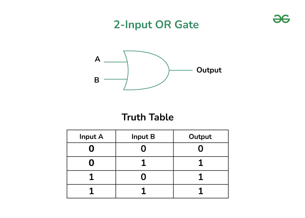
OR GATE
OR GATE is most widely used digital logic circuit. The output state of OR gate will be high i.e.,(1) if any of the input state is high or 1, else output state will be low i.e., 0.
The Boolean Expression for the OR gate is the logical addition of inputs denoted by plus sign(+) as
A + B = X
The value of X will be high(true) when one of the inputs is set to high (true).
Properties of OR Gate
An OR gate have the following two properties:
- It can have two or more input lines at a time.
- When all of the inputs to the OR gate are low or logic 0, the output of it is low or logic 0.
Summary
AND Gate : An AND gate outputs 1 only when all inputs are 1.
OR Gate : An OR gate outputs 1 when any input is 1.
NAND Gate: A NAND gate is the inverse of an AND gate. It outputs 0 only when all inputs are 1.
NOR Gate: A NOR gate is the inverse of an OR gate. It outputs 1 only when all inputs are 0.
EX-OR Gate (Exclusive OR): An EX-OR gate outputs 1 when an odd number of inputs are 1.
EX-NOR Gate (Exclusive NOR): An EX-NOR gate outputs 1 when an even number of inputs are 1, or when all inputs are 0.
Comments
Post a Comment